On this page
- Pressure, flow and volume are different
- Where the pressure goes
- Eleven common causes of pressure drop
- A practical pressure-diagnostic survey
- What is a hydro-pneumatic pumping system?
- When a hydro-pneumatic booster is likely appropriate
- When a booster is not the first solution
- How a hydro-pneumatic booster should be sized
- Hypothetical pressure and peak-flow example
- One building may need more than one pressure zone
- Integrating boosting with water treatment
- VFD energy performance: what can responsibly be claimed
- Does a hydro-pneumatic system prevent water hammer?
- Commercial-building booster specification checklist
- Commissioning a hydro-pneumatic booster system
- Operating and maintenance checks
- Indian site and climate considerations
- Frequently asked questions
- Diagnose first, then boost the right duty
- Sources and verification notes
Low building water pressure needs diagnosis before a larger pump. Check the incoming supply, storage, pipework and peak demand; then assess whether a hydro-pneumatic booster is appropriate.
For site support, see commercial pumping and pressurisation assessment. This guide explains the checks behind that decision.
Low pressure can originate at the incoming supply, elevation, undersized or obstructed pipework, dirty water-treatment equipment, a faulty valve, an empty tank, a poor control setting, a leak or a demand peak beyond the system's capacity. Adding a booster without locating the loss can waste energy, overload downstream pipework or leave the original fault untouched.
Consider a hydro-pneumatic or controlled booster system when measured inlet pressure plus the existing supply arrangement cannot provide the required pressure at the critical outlet during verified peak flow—and after restrictions, leaks, tank, treatment and valve problems have been ruled out. Size the system from peak flow and total required head, not horsepower, average daily consumption or floor count alone.
Pressure, flow and volume are different
Three quantities are often mixed together during troubleshooting:
- Pressure is the force per unit area available in the water system.
- Flow is the volume delivered per unit time.
- Stored volume is the amount available in a tank or vessel.
A gauge can show acceptable static pressure when every outlet is closed, yet pressure can collapse when water flows. That usually points to insufficient source capacity, excessive resistance, an undersized route, a pump problem or a combination of them.
Conversely, high pressure at a gauge does not guarantee adequate flow through a blocked filter, small branch pipe or partially closed valve.
Static pressure versus residual or dynamic pressure
- Static pressure: pressure measured at zero or negligible flow.
- Residual pressure: pressure remaining at a stated location while a stated flow is being delivered.
“We have 3 bar” is therefore incomplete. A useful reading states where, when, at what flow, with which source and tank level, and whether other outlets were operating.
Where the pressure goes
At a simplified level, the pressure available at a critical outlet is determined by:
Pump engineers express head in metres of the pumped liquid. KSB defines total head as energy per unit mass divided by gravitational acceleration and distinguishes pump head from system head. [Sources: KSB, Total Head] and [KSB, Head]
For freshwater calculations, a practical approximation is:
The more precise relationship is pressure increase = density × gravitational acceleration × head. KSB's pressure-booster design guidance uses 9.81 m/s² for gravitational acceleration and gives the same approximate 10 m-to-1 bar conversion for water. [Source: KSB, Planning Information for Pressure Booster Systems]
This approximation is useful for understanding elevation, but it is not a pump selection by itself.
Eleven common causes of pressure drop
1. Low or variable incoming pressure
Municipal or campus pressure can vary with time, upstream demand and the supply arrangement. If the pump selection assumes a best-case inlet reading, the system may fail at the lowest usable inlet condition.
Record inlet pressure over representative operating periods. If the building also uses borewell, tanker, underground-tank or roof-tank supply, document which source and water level were in service during each measurement.
Direct boosting from a public main must not be assumed permissible. The designer must check the local water authority, backflow requirements and the project's applicable plumbing rules. BIS identifies Part 9, Section 1 of NBC 2016 as covering water-supply design, multi-storey distribution, backflow prevention, inspection and maintenance. [Source: BIS, Guide for Using NBC 2016]
2. Elevation to upper floors
Water pressure is consumed in lifting water above the reference level. A fixture 20 metres above the booster needs approximately 2 bar merely to overcome that elevation, before pipe losses and the required residual outlet pressure are added.
Grundfos's commercial-building guidance defines static height as the elevation from the booster set to the highest tapping point and requires both static and dynamic losses to be calculated when sizing. [Source: Grundfos, Proportional Pressure in Water Boosting]
3. Simultaneous peak demand
Commercial demand is rarely flat. Hotels, restaurants, hospitals, offices, malls, schools and industrial facilities have different load patterns.
Pressure may appear satisfactory during a quiet inspection and fail when several high-flow uses overlap. The required design flow must account for the applicable plumbing method, measured operating profile, non-diversified process loads and future loads that the project has expressly included.
Average daily water consumption is useful for storage and resource planning. It does not establish the instantaneous booster duty.
4. Pipe friction and fittings
Moving water loses head through straight pipe and through valves, bends, tees, meters, backflow devices, strainers and other components. These dynamic losses increase with flow and fall to zero at zero flow.
That is why a building can show good pressure at night and poor pressure at peak use. Grundfos makes the same distinction between flow-independent static height and flow-dependent dynamic loss. [Source: Grundfos]
Pipe diameter, internal condition, length, material and the actual fitting schedule must be used in the hydraulic calculation. A generic percentage allowance may conceal the critical restriction.
5. Dirty or incorrectly sized treatment equipment
Water-treatment stages are part of the hydraulic route. Pressure can be lost across:
- strainers;
- media filters;
- activated-carbon filters;
- cartridge filters;
- softeners;
- UV reactors and other inline devices;
- control valves; and
- undersized treatment manifolds.
Measure pressure before and after each stage at the same operating flow. A rising differential pressure can point to loading or obstruction, but the alarm and service limit must come from the installed equipment's design and manual.
A booster installed after an undersized treatment train cannot make that treatment train pass more water without checking its permitted flow and pressure.
6. Partially closed, failed or misadjusted valves
A closed isolation valve, incorrect bypass position, sticking check valve, faulty pressure-reducing valve or undersized backflow device can create a large local loss.
Xylem's pressure-booster design example treats water-meter, backflow-preventer, static-elevation and friction losses as separate design components. This is a useful reminder to measure component losses instead of assigning every problem to the pump. [Source: Xylem Bell & Gossett, Domestic Water Pressure Booster Design]
7. Tank level or suction-side problems
An underground or break tank may be low, its level switch may be misbehaving, the suction line may be undersized or obstructed, or the pump may be drawing air.
The suction arrangement must be checked for the exact pump and installation. A discharge-pressure problem cannot be solved safely by ignoring inlet conditions, required submergence, net positive suction head, priming or dry-run protection.
8. Pump selected for the wrong duty
A pump must be evaluated at its operating point—the intersection of the pump and system characteristics—not by horsepower alone.
Possible problems include:
- insufficient head at peak flow;
- adequate head but insufficient flow;
- excessive head at low demand;
- operation far from the intended efficiency region;
- a worn impeller or internal clearances;
- incorrect rotation;
- wrong speed or impeller diameter;
- multiple pumps staging incorrectly; or
- a duty/standby arrangement mistaken for an additive-duty arrangement.
BEE's pumps and pumping-system guidance emphasises matching pump output to system needs and evaluating variable-speed control rather than relying on throttling or bypass. [Source: Bureau of Energy Efficiency, Pumps and Pumping System]
9. Control or pressure-sensor problem
A VFD can only respond to the information and logic provided to it.
Pressure may fluctuate because of:
- a drifting or incorrectly ranged sensor;
- a sensor installed at an unrepresentative location;
- an incorrect setpoint;
- unstable PID tuning;
- poor pump staging;
- a failed pressure vessel;
- minimum-speed or sleep-mode settings;
- electrical supply events; or
- conflicting local and remote controls.
Sensor position matters. Xylem's guide shows that a sensor at a remote critical point can account for variable distribution losses differently from a sensor mounted only on the booster discharge manifold. The right approach is project-specific and must consider sensor reliability and failure response. [Source: Xylem Bell & Gossett]
10. Leakage or unintended flow
A concealed leak, overflowing tank, open drain, passing bypass, leaking flush valve or uncontrolled process draw can consume capacity and reduce pressure elsewhere.
Compare tank levels, make-up flow, pump runtime and water-meter data during periods when legitimate demand should be low. Repairing the loss may remove the need for additional pumping.
11. A local outlet or equipment fault
If only one tap, appliance or zone is affected, inspect its branch:
- aerator or nozzle;
- flexible hose;
- local strainer;
- solenoid valve;
- pressure regulator;
- thermostatic mixing valve;
- service valve;
- equipment inlet specification; and
- pipe route.
A whole-building booster is not the first response to one blocked endpoint.
A practical pressure-diagnostic survey
Do not begin by choosing a pump. Begin by mapping the system.
Step 1: draw the water route
Show:
- source or incoming main;
- underground, break or roof tanks;
- transfer pumps;
- treatment equipment;
- existing booster set;
- risers and pressure zones;
- pressure-reducing valves;
- critical endpoints; and
- drain, bypass and recirculation routes.
Mark pipe sizes, elevations and known components.
Step 2: define the critical outlet
The critical outlet is not automatically the highest tap. It is the location with the most demanding combination of:
- elevation;
- route loss;
- required operating pressure;
- required flow; and
- business consequence of failure.
A remote kitchen appliance on the same floor can be more demanding than a nearby wash basin one floor higher.
Step 3: log pressure and flow together
At minimum, obtain coordinated readings at:
- incoming supply or source;
- pump suction;
- pump discharge;
- before and after major treatment stages;
- the base of critical risers;
- downstream of pressure-reducing valves; and
- the critical endpoint.
Record:
- time;
- source in service;
- tank level;
- static or flowing condition;
- measured flow;
- number or type of loads operating;
- pump number and speed;
- valve and bypass position; and
- alarm or abnormal condition.
Use calibrated or verified instruments of suitable range. A single unverified gauge cannot locate a system loss.
Step 4: compare quiet and peak conditions
| Observation | More likely direction for investigation |
|---|---|
| Low pressure even at zero flow | Low source pressure, elevation, PRV/setpoint, pump or gauge problem |
| Good static pressure, large drop as flow rises | Restriction, undersized route, source limitation or inadequate pump duty |
| Good booster discharge, poor remote pressure | Distribution friction, valve, zoning or local branch problem |
| Low suction and discharge together | Source, tank, suction route or transfer problem |
| High differential across a filter | Filter loading, incorrect valve position or undersized treatment stage |
| Pressure cycles rapidly at low demand | Pressure-vessel, pre-charge, sensor, control or minimum-flow issue |
| Lower floors high, upper floors low | Insufficient zoning, elevation and distribution-design problem |
| Only hot water is weak | Water-heater, hot-water branch, mixing valve or hot-water recirculation issue |
| One appliance is weak | Local connection, inlet component or equipment requirement |
This table is diagnostic guidance, not a final diagnosis. Several causes can coexist.
What is a hydro-pneumatic pumping system?
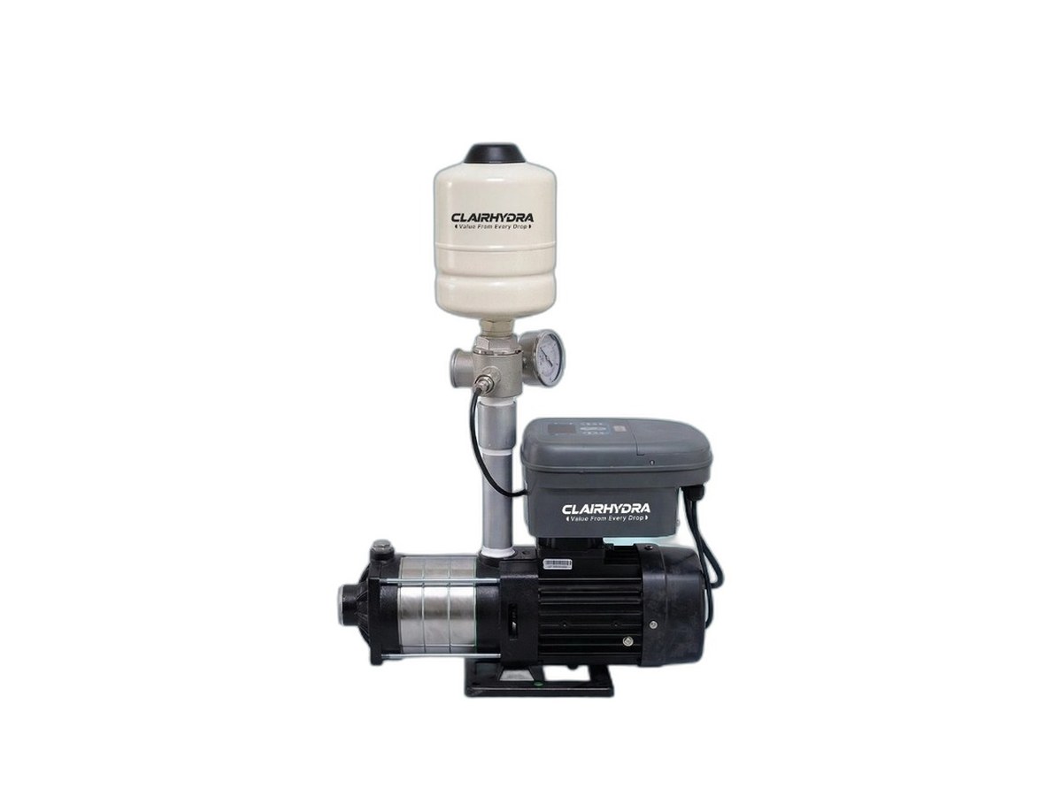
In commercial-building practice, a hydro-pneumatic pressure-boosting package commonly combines:
- one or more booster pumps;
- a hydropneumatic or diaphragm pressure vessel;
- pressure sensing;
- fixed-speed pressure switches or variable-speed drives;
- a controller;
- suction and discharge manifolds;
- isolation and check valves;
- gauges or transmitters;
- protection and alarm functions; and
- pressure-relief provisions where required by the design.
The exact definition and arrangement vary by supplier. Some small “all-in-one” boosters have an integrated vessel; larger commercial sets may use multiple pumps and a separately selected vessel.
What the pressure vessel does
The vessel contains water and a compressible gas cushion separated by a bladder or diaphragm in many designs. Subject to the manufacturer's configuration, it can:
- provide a small draw volume;
- buffer brief pressure changes;
- reduce rapid pump starts and stops; and
- support stable control at low demand.
Pentair's current variable-speed booster manual states that its integrated expansion tank helps maintain output pressure and minimises pump start/stop cycling. Its pre-charge is tied to that product's chosen setpoint and installation instructions. Those product-specific values must not be copied to another vessel or system. [Source: Pentair Sta-Rite Variable-Speed Booster IOM]
A pressure vessel is not a substitute for adequate water storage or a pump capable of meeting the design duty.
Fixed-speed and variable-speed arrangements
| Feature | Fixed-speed start/stop | Variable-speed / VFD |
|---|---|---|
| Pump response | Pump runs at fixed rotational speed when called | Controller varies motor speed within approved limits |
| Pressure behaviour | Usually varies between start and stop thresholds | Can control towards a setpoint or control curve |
| Vessel role | Often provides more drawdown between cycles | Often smaller buffering role, but must still be selected correctly |
| Variable demand | May stage pumps or cycle more often | Can match pump output more closely to changing demand |
| Complexity | Simpler controls | Sensors, drives, logic, EMC/electrical and tuning require competent design |
| Energy outcome | Depends on duty and control | Can reduce throttling and excess head, but savings are site-dependent |
| Best choice | Stable or simple duty where cycling is acceptable and correctly managed | Variable load where hydraulic analysis supports speed control |
BEE explains that speed adjustment can reduce the energy imparted to the fluid instead of dissipating it through throttling or bypass, but also cautions that speed control is not suitable for every pumping system—particularly where high static head severely limits the useful speed range. [Source: BEE, Pumps and Pumping System]
Therefore, “VFD” is a control option, not proof that a system is efficient.
When a hydro-pneumatic booster is likely appropriate
Pressure boosting becomes a reasonable solution when the survey confirms one or more of these conditions:
- incoming or gravity pressure is insufficient at the critical outlet;
- upper floors cannot retain the required residual pressure at peak demand;
- the building's source pressure varies beyond what passive regulation can accommodate;
- demand varies widely and a controlled multi-pump set can match the load;
- a treated-water tank must supply several pressurised endpoints;
- the roof-tank elevation cannot provide the equipment's required pressure;
- a new facility has a defined peak-flow and pressure duty that gravity alone cannot meet; or
- an existing booster is demonstrably undersized, poorly controlled or beyond economical correction.
Grundfos identifies direct, zone-divided, roof-tank and series booster configurations for different building arrangements. The applicable configuration depends on the source, building height, pressure limits and local rules. [Source: Grundfos, Constant Pressure]
When a booster is not the first solution
Do not specify a new hydro-pneumatic set until these possibilities are resolved:
- dirty cartridge or media filter;
- closed or faulty valve;
- undersized local branch;
- leaking system;
- inadequate raw or treated-water storage;
- source supply too small for the required volume;
- transfer pump unable to refill the break tank;
- water-treatment plant unable to produce the required peak or recovery volume;
- faulty gauge, sensor or setpoint;
- one defective appliance connection;
- air ingress or suction problem;
- pressure-reducing valve malfunction; or
- an endpoint requirement that exceeds the connected pipework or equipment rating.
Boosting pressure cannot create source water, increase tank volume or safely force an undersized treatment unit beyond its approved flow.
How a hydro-pneumatic booster should be sized
Correct selection requires two primary hydraulic coordinates:
- design peak flow, and
- required pump head at that flow.
It also requires checks beyond that single duty point.
1. Establish design peak flow
Use the applicable building-plumbing calculation, supported where possible by measured or modelled load profiles. Separately add process loads that do not follow ordinary fixture diversity.
Examples can include:
- laundry machines;
- kitchen spray stations;
- dishwashers and glasswashers;
- tank filling;
- cleaning systems;
- cooling or process make-up; and
- simultaneous regeneration or backwash if the design permits it.
State which loads are simultaneous and which are interlocked or scheduled.
2. Calculate required discharge head
At the design peak, include:
- elevation from the hydraulic reference point to the critical outlet;
- required residual pressure at that outlet;
- pipe and fitting friction;
- meter, backflow, treatment, heat-exchanger, valve and equipment losses;
- the minimum credible inlet or suction condition; and
- design margins that are explicitly justified.
For a booster receiving positive inlet pressure:
For a pump drawing from a vented break tank, the tank water level and suction arrangement replace the municipal-inlet assumption. The complete total dynamic head and suction check must be calculated.
3. Check the whole operating range
The engineer should verify:
- minimum and normal demand;
- design peak;
- pump curve and efficiency region;
- minimum speed or stable operating limit;
- pump staging and de-staging;
- no-flow or sleep behaviour;
- available and required NPSH;
- maximum system and component pressure;
- pressure at lower and upper zones;
- vessel drawdown and pre-charge;
- motor, VFD and electrical supply;
- standby or redundancy requirement;
- water temperature and material compatibility;
- noise, vibration and plant-room environment; and
- failure and restart behaviour.
KSB notes that water-supply pump type depends on flow, head and installation conditions. [Source: KSB, Water Supply Pump]
Hypothetical pressure and peak-flow example
The following example illustrates the method. It is not a DhwaNeer project and is not a pump selection.
Assume a commercial facility has:
- a measured design peak flow of 3.0 L/s;
- a critical outlet 18 m above the booster;
- an equipment-approved required residual pressure of 1.5 bar at that outlet;
- calculated pipe, valve and treatment losses of 0.7 bar at 3.0 L/s; and
- a measured minimum usable booster-inlet pressure of 1.2 bar during the peak period.
Step A: elevation pressure
Using the approximate 10 m water head = 1 bar relationship:
Step B: required discharge pressure at design peak
Step C: required differential boost
The preliminary hydraulic duty is therefore approximately:
This is not enough to order a pump. The engineer must still review the pump curve, actual tank/source configuration, inlet hydraulics, NPSH, minimum flow, component pressure ratings, diversity method, lower-floor pressure, control method, redundancy and operating range.
If the same booster were fed from a vented break tank rather than a positively pressurised inlet, the calculation would change. If demand fell, the 0.7 bar design-flow loss would also fall; the control strategy should not blindly reproduce peak-flow discharge pressure at every low-flow condition.
One building may need more than one pressure zone
A single high-pressure booster serving every floor can create excessive pressure at lower levels while only just meeting the upper-floor requirement.
Possible arrangements include:
- separate booster sets for different zones;
- pressure-reducing valves for lower zones;
- intermediate break tanks;
- roof-tank supply with local upper-zone boosting; or
- series boosting designed for the specific building.
Grundfos lists zone-divided systems and intermediate break-tank arrangements among standard commercial-building configurations. [Source: Grundfos, Constant Pressure]
Zoning must consider the maximum allowable pressure of pipes, fittings, heaters, treatment equipment and appliances—not only whether the top floor receives water.
Integrating boosting with water treatment
DhwaNeer's WATERS method treats pumping as part of the complete route from source and storage through treatment to point of use.
The design should answer:
- Is the booster before or after treatment?
- Can every treatment component pass the booster design flow?
- What is each component's clean and dirty pressure loss?
- Can a softener, filter or UV unit tolerate the maximum pressure?
- Will filter backwash or softener regeneration interrupt supply?
- Is treated-water storage sufficient for production and peak demand?
- Does low tank level stop the booster before dry running?
- Can untreated water cross-connect through a bypass?
- Are wetted materials suitable for potable or process water?
- Does the pump arrangement risk drawing directly against a production process not designed for suction?
For an RO system, distribution demand is normally decoupled from membrane production by appropriately designed product storage and pumping. A distribution booster should not be assumed to pull more permeate through the membranes on demand.
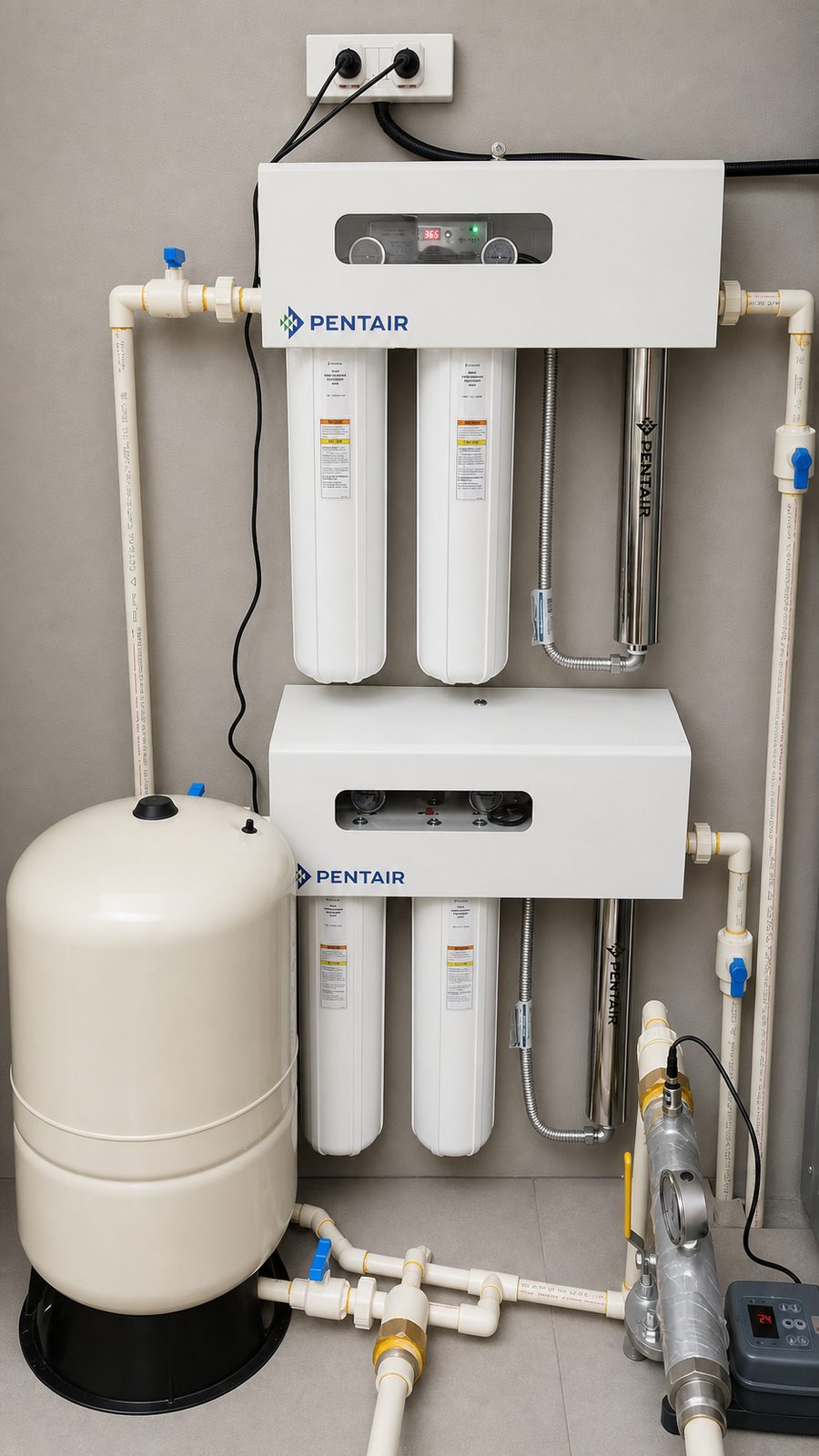
DhwaNeer assesses the source, storage, pressure zones, demand and treatment interfaces before recommending a commercial hydro-pneumatic system. The commercial pumping and pressurisation service page explains the assessment, installation, commissioning and support scope.
Explore DhwaNeer's broader water-treatment portfolio. Discuss comparable pumping references and the proposed scope with the team; treatment projects alone do not demonstrate booster-system performance.
VFD energy performance: what can responsibly be claimed
A variable-speed booster can reduce pump speed when demand or required head falls. BEE describes speed adjustment as an efficient method of controlling pump flow compared with wasting head through throttling or bypass. [Source: BEE]
However, actual energy performance depends on:
- load profile;
- ratio of static to friction head;
- pump selection and staging;
- motor and drive efficiency;
- sensor position;
- control curve;
- minimum-speed limits;
- inlet-pressure variation;
- pressure-reducing-valve losses; and
- operating hours.
Xylem's design guide specifically recommends evaluating pump oversizing, variable head loss, pressure-reducing-valve losses and changing suction pressure when assessing variable-speed boosting. [Source: Xylem Bell & Gossett]
Do not promise a generic energy-saving percentage. Compare measured or modelled annual duty profiles for the actual alternatives.
Does a hydro-pneumatic system prevent water hammer?
Not automatically.
Water hammer is a transient pressure event caused by a rapid change in flow velocity, such as fast valve movement or a pump trip. A correctly selected vessel, controlled acceleration/deceleration, appropriate valves and transient-control devices may reduce particular events, but protection depends on the complete pipe system and event.
KSB's water-hammer guidance treats surge pressure as a system-transient problem requiring analysis of the pipeline, pumps, valves and protective measures. [Source: KSB, Surge Pressure]
Pentair states that soft starts and stops on the cited booster can minimise water hammer. “Minimise” is not “eliminate,” and that statement applies to the specified product and operating event. [Source: Pentair Sta-Rite Booster IOM]
If the building experiences banging pipes, valve slam or damaging pressure spikes, perform a transient investigation instead of merely raising or lowering the pressure setpoint.
Commercial-building booster specification checklist
Before comparing proposals, give each supplier the same verified design basis:
- system schematic and pressure zones;
- source and supply arrangement;
- minimum, normal and maximum inlet pressure;
- tank levels and suction configuration;
- design peak and load profile;
- critical outlet and elevation;
- required residual pressure and flow;
- calculated pipe and component losses;
- fluid quality and temperature;
- treatment equipment and pressure limits;
- duty, assist and standby philosophy;
- permissible minimum and maximum pressure;
- vessel standard, volume and replaceable-bladder requirement if applicable;
- VFD and control philosophy;
- sensor locations and redundancy;
- dry-run, low-level, high-pressure and motor protection;
- power supply, panel rating and electrical interfaces;
- BMS or remote alarm points;
- noise, vibration, ventilation and flood-protection requirements;
- potable-water material or certification requirements;
- installation, testing and commissioning scope;
- spare parts, warranty and service response; and
- applicable local authority and plumbing requirements.
Horsepower should be an output of selection—not the initial design brief.
Commissioning a hydro-pneumatic booster system
Commissioning must validate the integrated system under defined conditions.
Pre-start checks
- verify approved pump, motor, vessel, sensor and panel identities;
- check foundations, alignment, anchors and pipe supports;
- confirm suction and discharge pipework is complete, flushed and leak-tested;
- confirm the source, tank and minimum level are available;
- verify valve positions and check-valve orientation;
- confirm electrical protection, phase sequence, rotation and earthing through qualified personnel;
- confirm vessel pre-charge using the exact manufacturer procedure with the water side safely depressurised;
- verify gauge and transmitter calibration status;
- confirm pressure-relief and maximum-pressure protection;
- confirm venting or priming requirements; and
- test dry-run and low-level permissives before risking equipment.
Functional and performance checks
- record suction, discharge and remote pressure at no flow, minimum flow and representative loads;
- measure or verify flow at the defined duty condition;
- confirm each pump starts, stops, stages, de-stages and alternates as designed;
- verify duty/standby or duty/assist logic;
- test VFD ramp, minimum speed, sleep and wake behaviour;
- check pressure stability during rapid but representative demand changes;
- confirm the critical outlet retains the agreed residual pressure;
- confirm lower zones do not exceed permitted pressure;
- test alarms, sensor failure, low tank level, high pressure, overload and power-restoration response;
- inspect noise, vibration, leakage and abnormal heating;
- confirm treatment-stage differential pressures remain acceptable at design flow;
- record vessel and cycling behaviour at low demand; and
- retain the final setpoints and commissioning baseline.
Do not commission only at the discharge manifold. The project objective is pressure at the defined points of use.
Operating and maintenance checks
The plant-specific O&M manual should set frequencies and limits. Typical record categories include:
- inlet, suction, discharge and remote pressure;
- pump speed, current, run hours and start count;
- flow and demand period;
- tank level;
- vessel pre-charge check by the approved isolated procedure;
- filter and treatment differential pressures;
- leak and abnormal-noise inspection;
- alarm and trip history;
- PRV and check-valve condition;
- sensor and gauge calibration;
- ventilation and panel condition; and
- alternation and standby-pump proving.
Rapid cycling, unstable pressure, unusual vibration, repeated dry-run trips, rising current or loss of remote pressure requires investigation. Do not repeatedly increase the setpoint to hide a hydraulic or maintenance fault.
Indian site and climate considerations
There is no single “Indian condition.” Coastal, arid, humid, high-altitude, hot and monsoon-affected sites impose different requirements.
For the actual city and plant room, verify:
- manufacturer ambient-temperature and humidity limits;
- ventilation and heat rejection for motors and VFDs;
- enclosure and corrosion protection;
- flood level and drainage, especially for basement installations;
- power quality, outage and restart strategy;
- tanker, municipal, borewell or mixed-source operating logic;
- seasonal source and filter-loading changes;
- roof-tank and pipe exposure to heat;
- maintenance access during heavy rain or site shutdown; and
- local service and critical-spares availability.
Use the nameplate and manual for the exact equipment. For example, Pentair's cited small booster has explicit liquid and ambient limits and is specified for indoor installation; those limits are product-specific and cannot be generalized to all commercial packages. [Source: Pentair Sta-Rite Booster IOM]
Frequently asked questions
What is the difference between a booster pump and a hydro-pneumatic system?
A booster pump is the machine that adds head. A hydro-pneumatic system normally adds a pressure vessel, sensing, controls, protection and associated valves or manifolds to manage pressure and pump operation. Supplier terminology varies, so compare the component and control schedule.
How do I know whether my building pressure is too low?
Compare measured residual pressure and flow at the critical outlet with the applicable fixture, appliance, process and plumbing requirements. Record the inlet and pump conditions at the same time. Static pressure alone is insufficient.
Can I select a booster by the number of floors?
No. Floor count helps estimate elevation but does not establish peak flow, floor-to-floor height, pipe loss, inlet pressure, endpoint requirement, zoning, tank arrangement or treatment losses.
Can I select a booster from daily water consumption?
No. Daily volume does not establish instantaneous peak flow. Use the applicable diversity method, process loads and operating profile.
Does a VFD maintain exactly the same pressure everywhere?
No. It controls pressure at or relative to its sensor and control strategy. Pressure elsewhere still changes with elevation and distribution losses. Sensor placement and zoning matter.
Will a larger pressure tank fix low peak pressure?
Not if the source, pump or piping cannot sustain the required duty. A vessel provides finite drawdown and buffering; it does not replace adequate pump flow, source volume or pipe capacity.
Should the booster be installed before or after water treatment?
It depends on source pressure, treatment pressure requirements, clean/dirty losses, storage, water quality and distribution arrangement. The whole treatment and pumping train must be designed together.
Why does pressure drop when a filter is installed?
Every inline component creates some loss when water flows. A dirty, undersized or incorrectly valved filter can create excessive loss. Measure its differential pressure at a known flow and compare it with the approved design and manufacturer limit.
Why is pressure high at night and low during business hours?
At low demand, flow-dependent friction losses are small. During peak demand, those losses increase and the source or pump may also be unable to maintain the required duty. Coordinated pressure and flow logging will distinguish the causes.
Do I need separate pumps for every floor?
Usually not. Buildings may use a common set, pressure zones, PRVs, intermediate storage or a combination. Selection depends on height, pressure limits, demand and resilience.
Does a hydro-pneumatic system eliminate water hammer?
No system should be sold on that universal promise. Pump ramps and vessels can mitigate particular transients, but valve actions, pump trips, pipe velocity, wave behaviour and protection devices must be evaluated for the actual system.
Can an existing booster be retrofitted with a VFD?
Sometimes, but first check the motor, pump curve, insulation and cooling, minimum speed, control sensor, vessel, electrical harmonics and protection, static-head ratio, operating profile and economic case. A drive alone does not correct an unsuitable pump or pipe network.
Diagnose first, then boost the right duty
A dependable pressure solution follows this sequence:
- map the complete water route;
- identify the critical outlet;
- measure static and residual pressure with flow;
- capture the real peak-demand condition;
- quantify elevation and every important loss;
- correct restrictions, leaks and control faults;
- calculate peak flow and total dynamic head;
- evaluate boosting, storage and pressure zoning together;
- select pumps, vessel, sensors and controls across the operating range; and
- commission at the critical points of use.
DhwaNeer designs pumping and pressurisation as part of the complete commercial water train—from source and storage through filtration, softening or RO to treated storage and point-of-use delivery.
Sources and verification notes
This article was fact-checked on 25 July 2026 using Indian standards and energy-efficiency material plus primary pump-manufacturer engineering references. Manufacturer sources explain hydraulic and equipment principles but do not constitute an endorsement of any brand or a design for DhwaNeer's projects.
- Bureau of Indian Standards: National Building Code of India 2016 overview
- BIS: Guide for Using National Building Code of India 2016
- Bureau of Energy Efficiency: Pumps and Pumping System
- Grundfos: Constant-pressure boosting configurations
- Grundfos: Static and dynamic losses in commercial water boosting
- Xylem Bell & Gossett: Domestic Water Pressure Booster Design
- KSB: Planning Information for Pressure Booster Systems
- KSB: Total Head
- KSB: Head
- KSB: Water Supply Pump
- KSB: Surge Pressure
- Pentair Sta-Rite: Variable-Speed Booster Pump Installation and Operating Manual